 Home
| What's New
| Features
| Gallery
| Reviews | Reference
| Forum |
Search
Home
| What's New
| Features
| Gallery
| Reviews | Reference
| Forum |
Search|
Home
| What's New
| Features
| Gallery
| Reviews | Reference
| Forum |
Search |
UNDERCARRIAGE DETAILS
NOSE GEAR
Things of particular interest
in this area:
(Press "Back" on your browser to return to this
list.)
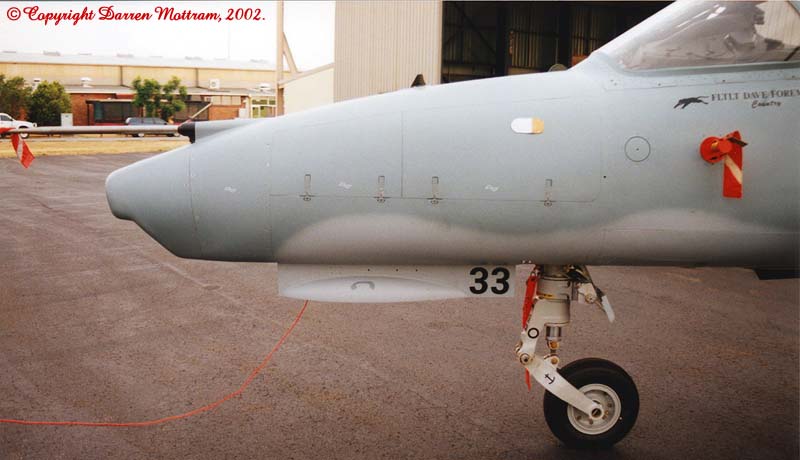
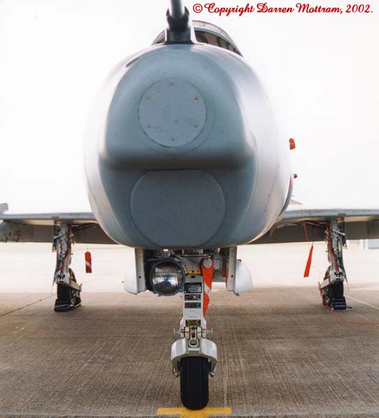
1/ The nose gear doors do not *quite* hang vertically. They usually have a slight inward slant to them. (Photo 5, Photo 6)
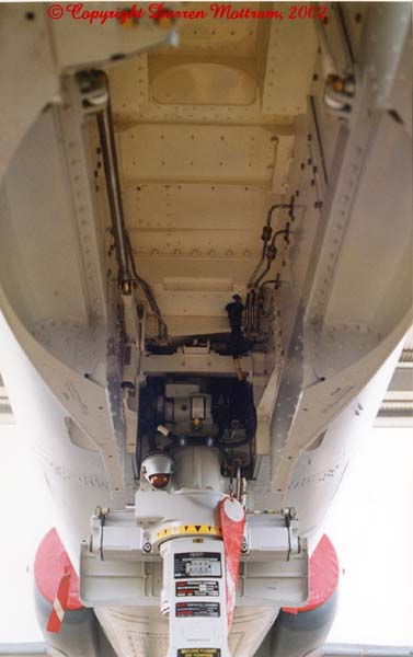
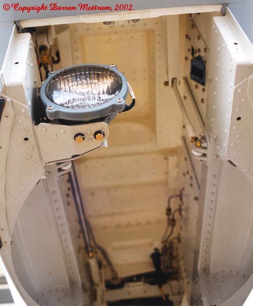
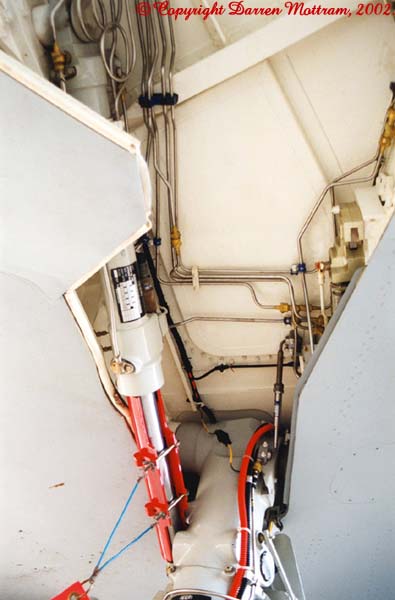
2/ The internal surfaces of the wheel well are painted gloss white. Anything which is external to this (gear doors, struts etc.) is painted Light Aircraft Grey, gloss epoxy BS 381C-627G. (Visible in almost all photos on this page.)
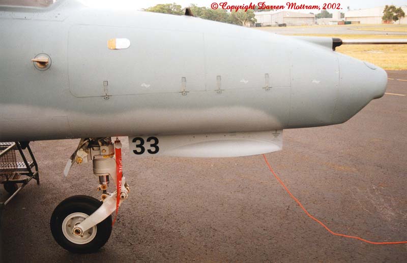
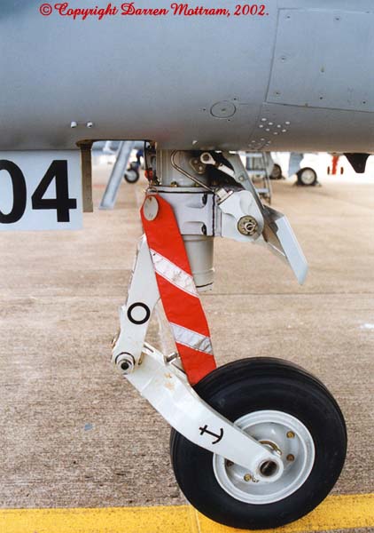
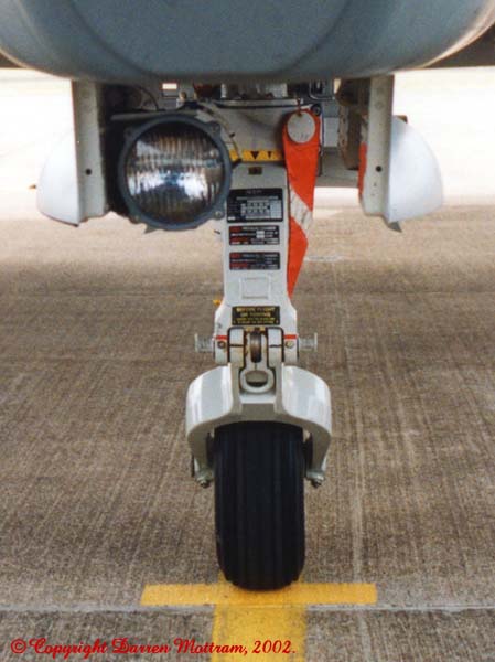
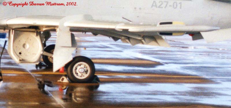
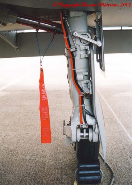
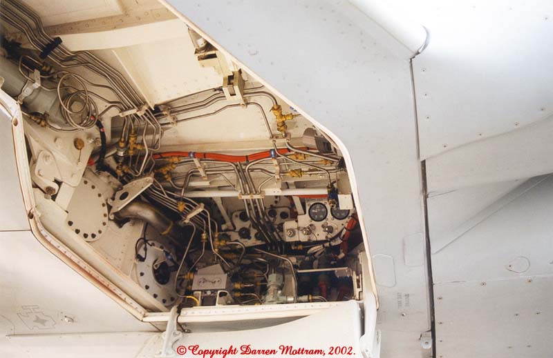
3/ Note the nose wheel steering unit fitted to the Mk 127 on the upper rear of the strut and the larger rear door to accommodate it. (Photo 1, Photo 2, Photo 3, Photo 4, Photo 7)
4/ The landing light is mounted on the front of the RH door. (Photo 5, Photo 6, Photo 8)
5/ Note the bulges in the doors to allow room for the nose wheel when retracted. (Visible in almost all photos here.)
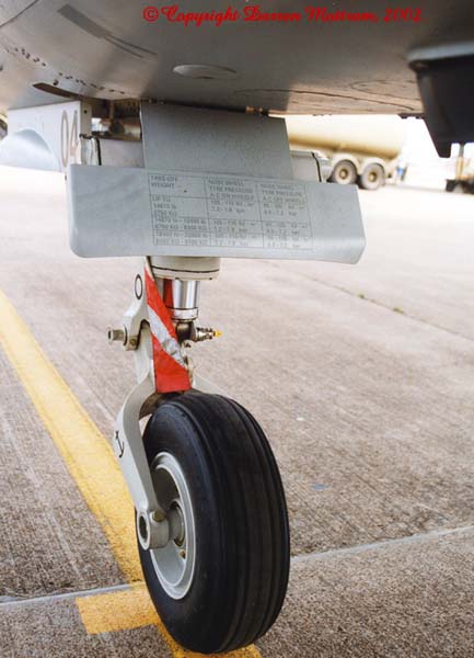
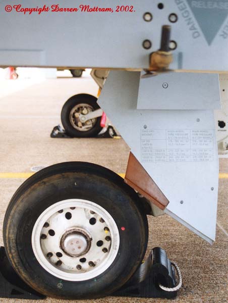
6/ Each undercarriage
unit has a tyre pressure table on one of the doors. This can be either
counter shaded grey or black. (Photo
4)
|
|
|
|
|
|
 |
 |
 |
 |
 |
|
|
|
|
|
|
|
|
|
|
|
|
|
|
|
|
||
 |
 |
 |
||
|
|
|
|
|
|
|
|
|
|
|
|
|
|
|
|
|
|
|
|
|
|
|
|
Things of particular interest
in this area:
(Press "Back" on your browser to return to this
list.)
1/ The main gear legs seem to have a slight outward cant to them and the bottom fork "straightens up". (Photo 11)
2/ The internal surfaces of the wheel well are painted gloss white. Anything which is external to this (gear doors, struts etc.) is painted Light Aircraft Grey, gloss epoxy BS 381C-627G. (Visible in almost all photos on this page.)
3/ LH flipper door (front of A/C to the left). (Photo 14)
4/ LH inner wheel well. (front of A/C to the left) (Photo 15)
5/ LH outer wheel well. (front of A/C to the right) (Photo 16)
6/ RH inner wheel well. (front of A/C to the right) (Photo 17)
7/ Note the large (about 1cm or so) gap between the fuselage and where the wing joins it underneath the fuselage, in front of the wheel wells. This has a rounded rubber strip in it to seal the gap but it is very noticeable. (Photo 17)
8/ Each undercarriage
unit has a tyre pressure table on one of the doors. This can be either
counter shaded grey or black. (Photo
10,
Photo 13)
|
|
|
|
|
|
 |
 |
 |
 |
 |
|
|
|
|
|
|
 |
 |
 |
 |
|
|
Text and Images Copyright © 2002 by Darren
Mottram
Back to Hawk Walk Around Main Page
Used with the permission of BAE SYSTEMS and the RAAF Page Created Saturday 02 February, 2002 This page last updated on Saturday 02 February, 2002 Back to HyperScale Main Page Back to HyperScale Reference Library
|